
Ⅰ. Overview
We will practice restoring the MBR and VBR using a DISK sample image. After the restoration, we will practice finding the Data Area in FAT and NTFS, and examine the structure.
Ⅱ. DISK Exercise - MBR, VBR Restore
We will restore the MBR and VBR using VBR backup via HxD with the sample DISK image.
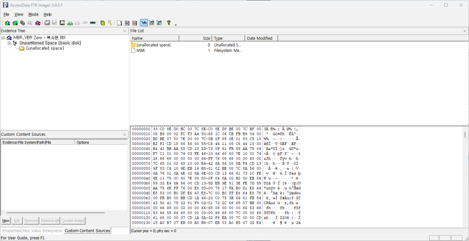
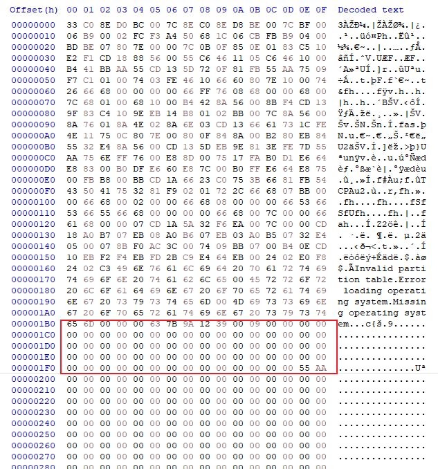
In the two images above, you can see that the MBR and VBR are corrupted. Normally, the 0th sector contains MBR information, and you can see that the last partition-related information in the MBR, which is composed of 512 bytes, has been lost. In this restoration exercise, we will first locate the backup sector of the VBR. Second, we will distinguish whether the partition in the VBR is NTFS or FAT. Third, we will calculate the total sector size of the partition in the VBR and use this information to determine the location of the original VBR. Fourth, we will copy the backup VBR sector to the original VBR location and restore it, and then recover the partition information in the MBR based on the relevant information. We will proceed in this order.
Finding VBR backup sectors
There are several ways to find the backup sector in VBR. I would like to introduce one method that uses a signature. If you search for hexadecimal 55 AA in HxD, you will find the following:
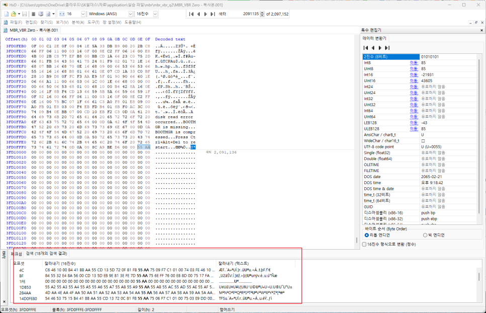
This is how it works. As you search through the results, you'll find
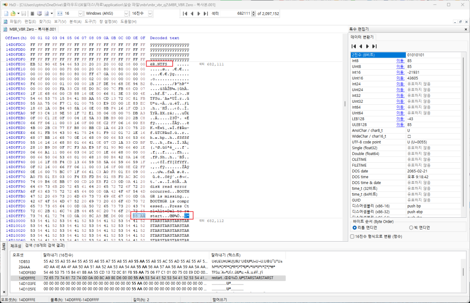
In this case, the last 2 bytes are 55 AA and we can see 'Uª'. This is the signature. It is important to remember that the hexadecimal value 55 AA is the signature, not just the character form. If you look at the red part above, you can see that it is NTFS. There are many related blogs about the NTFS VBR structure, so I think you will understand it better if you refer to them.
Restore NTFS VBR
For NTFS, the backup sector is usually the last sector in the NTFS partition. Therefore, if the partition sector size can be determined from the backup sector, the location of the original backup sector can be determined.
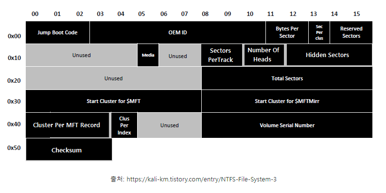
If you look at this structure, you will see that the information for Total Sectors is contained in a total of 8 bytes, ranging from 0x20 to 0x27 in VBR.
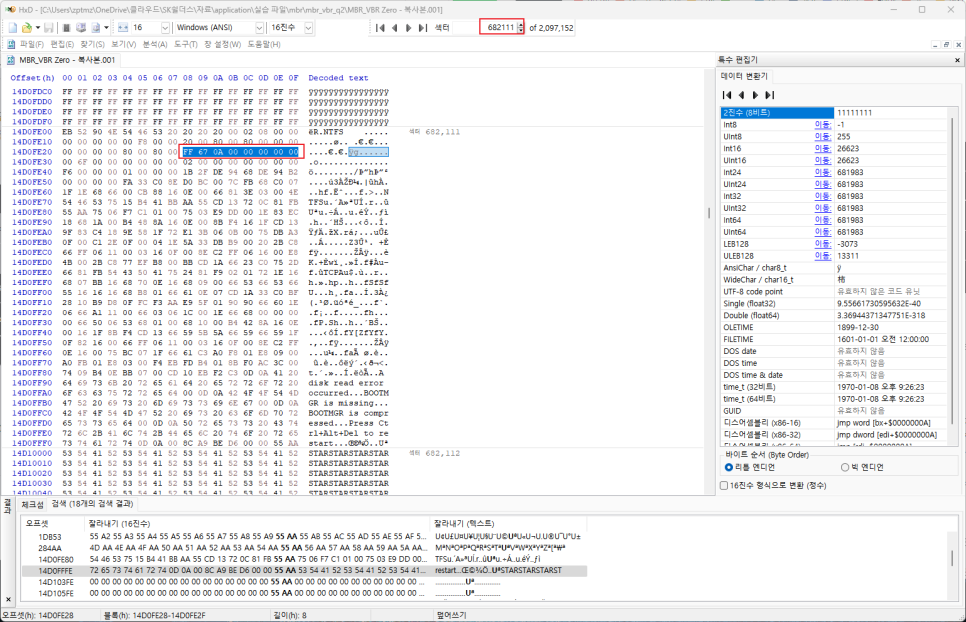
In the above image, A67FF is the total number of sectors in the partition as Little Endian. When calculated, the value obtained is '681,983'. Since the current location of the backup sector is '682,111', subtracting the total number of sectors from this value yields '128', which is the starting sector of the original VBR.
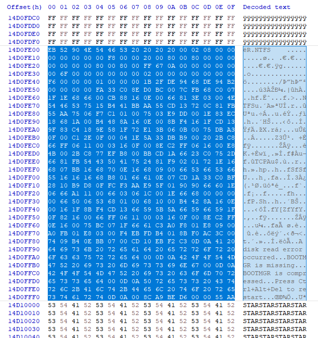
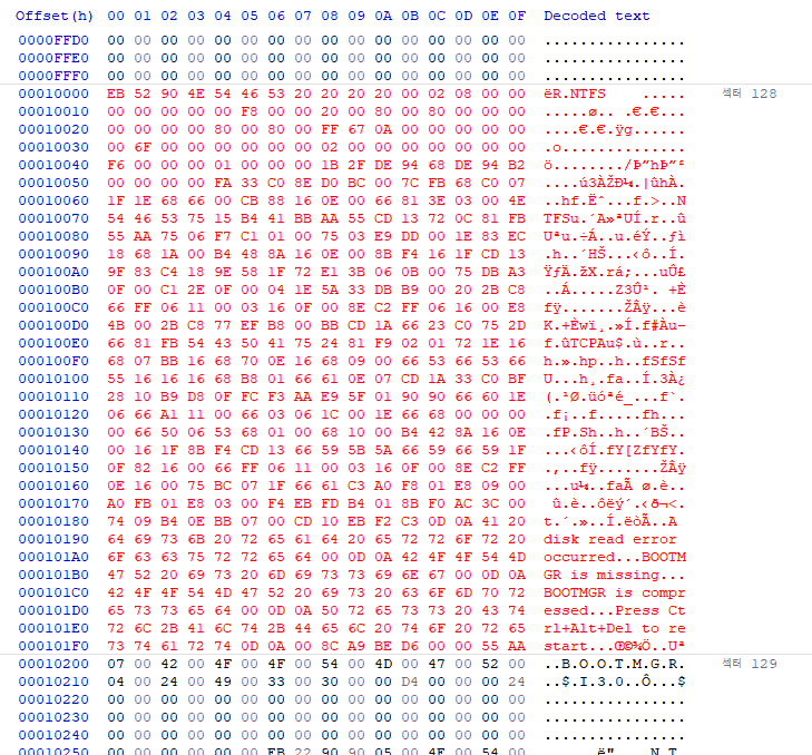
After copying the backup VBR, simply paste it into sector 128 and save it.
Restore NTFS partition to MBR
Now, we will use these values to restore the MBR.
[SK Shillers SeSAC Sungdong 1st Batch] ZIP Structure, DISK
As mentioned in the previous post, MBR contains information about each partition in 16-byte increments from 446 to 510 bytes. For the NTFS partition starting at sector 128, we will insert the necessary information into the first 16 bytes of MBR. In fact, we only need 1 byte, 4 bytes, 8 to 11 bytes, and 12 to 16 bytes, so we will re-enter only these information. We will change the Boot Flag to 80 in 1 byte, and the file system type to 07, which means NTFS, in 4 bytes. The partition start address in 8 to 11 bytes will be 80, which is converted from sector 128 in hexadecimal, and the last 12 to 16 bytes will be A67FF, which is the size of the partition.
※ Please note that when substituting, the actual notation is Big Endian, as it is read as Little Endian at this time.
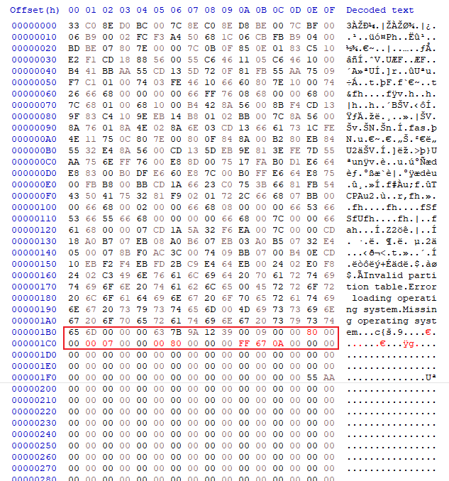
Once you have inserted and saved it, check with the FTK Imager to see if the restoration was successful.
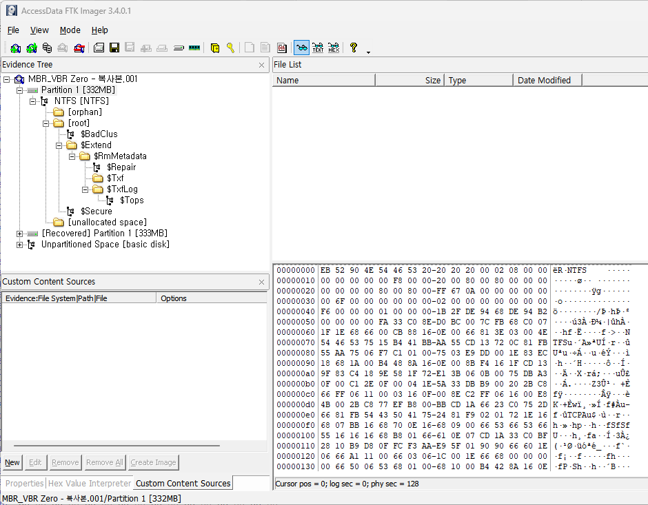
You can see that the recovery is successful. Then, you can proceed with FAT in the same way.
FAT recovery in progress
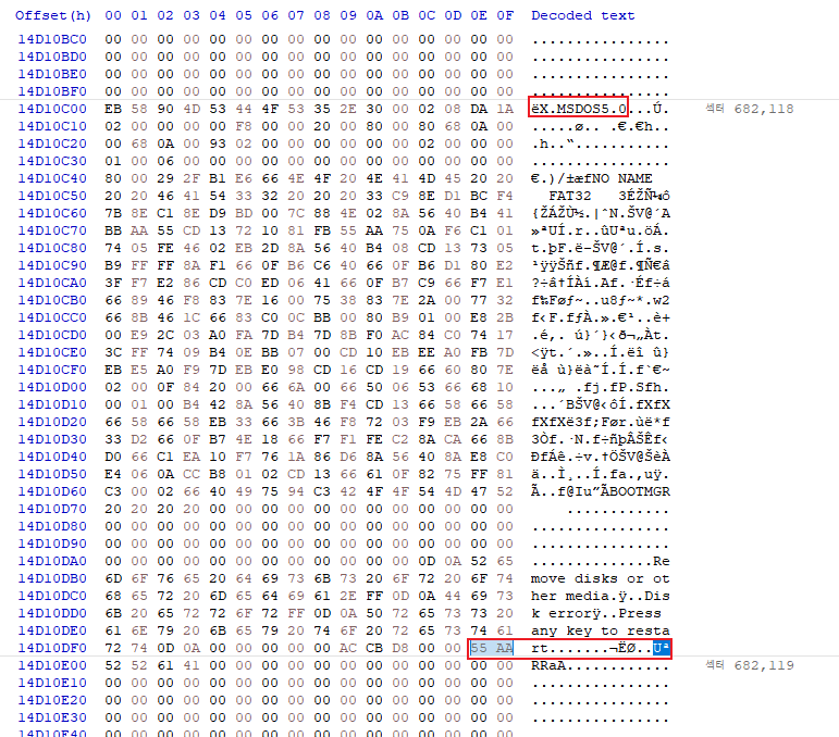
Find the backup VBR in this way, and copy and paste the backup VBR at '682,112', which is -6 from here.
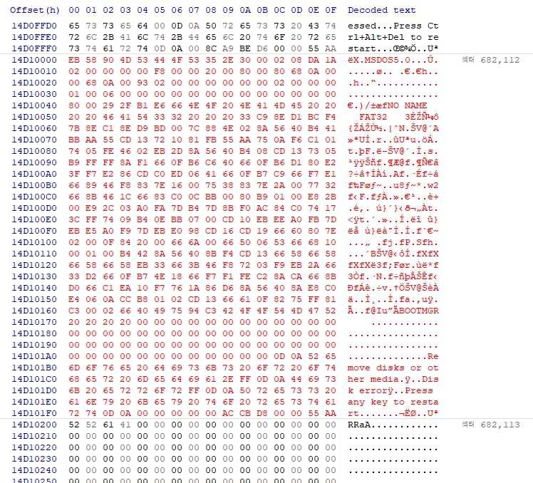
After that, if you restore the MBR again, you simply need to enter the boot flag 80, type 0B or 0C, the start address '682,112' converted to A6880, and the sector size.
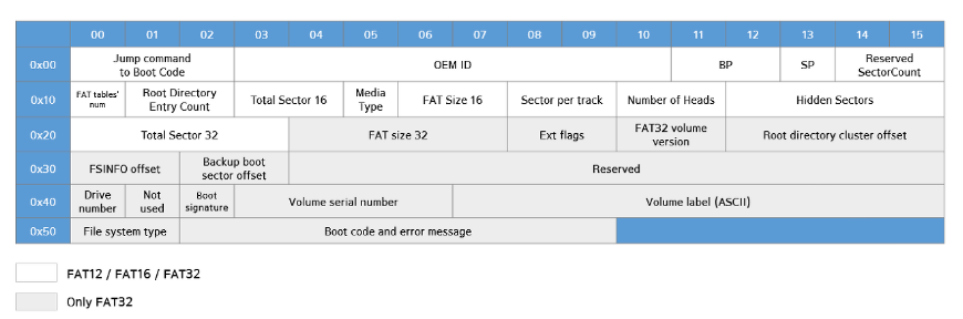
Source hec-ker.tistory.com / Attached below
If we calculate from the above structure that the entire partition sector size is 4 bytes from 0x20, it is A6800. Now, if we enter the value into the MBR,
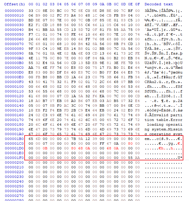
You should be able to enter this. Now, after saving, if you check with FTK Imager again,
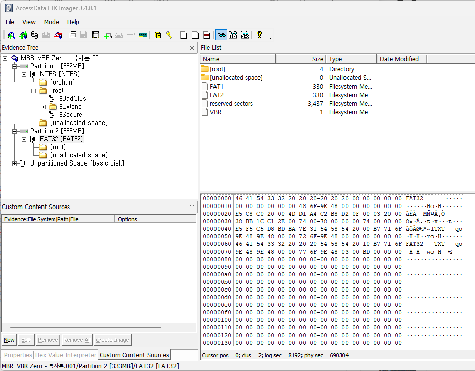
You can see it restored so well.
Ⅲ. DISK Exercise - Finding the Data Area
As I mentioned briefly in a previous post, the way to find the DataArea in FAT32 is as follows: FAT32 has a structure of VBR (reserved area) - FAT1 & FAT2 - The MFT appears. Then, in the start sector of the VBR, there is a reserved area and FAT1 & If we add the FAT2 sector size, would that result in the location of the Data Area?
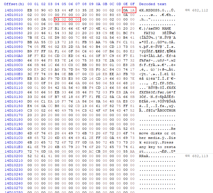
If we calculate, the information for the number of reserved sector is 0x0E~F and 6,874. Since the FAT sector size is 0x24~7, it is 659. However, since there are FAT1 and 2, if we multiply by 2, it becomes 1,318. Now, if we add all these values, we get 6,874 + 1,318 + 682,112 (the starting sector of FAT - VBR) which is 690,304. Now let's go to that sector.
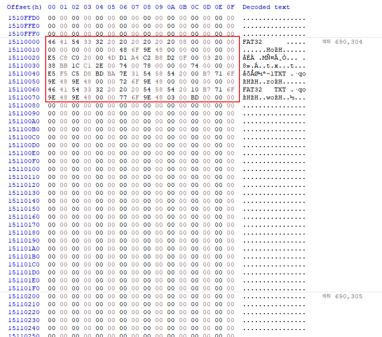
We were able to find the Data Area of the restored FAT32. For FAT32, the structure of the Data Area is
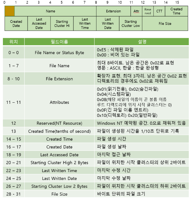
Source dotaky99.tistory.com / Link attached below
[File System] FAT32 - Part 3 (Data Area, restore)
It looks like this. The important thing to note is that we need to distinguish between the SFN (Short File Name) structure and the LFN (Long File Name) structure, which can be distinguished by a 12-byte value. The reason for distinguishing between these two is because the structures are different.
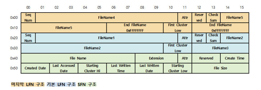
Source blog.forensicresearch.kr / Link attached below
Directory Entry Analysis - SFN, LFN
By default, 32 bytes are separated, and since the SFN structure is as shown below, we can examine it. However, in the case of LFN, there are more things to consider. First, if 11 bytes out of 32 bytes are 0x0F, then those 32 bytes are the LFN structure. Then, if we look at the 1 byte at the 0x0 position, we can see that it is a Sequence Number, and this value is important.
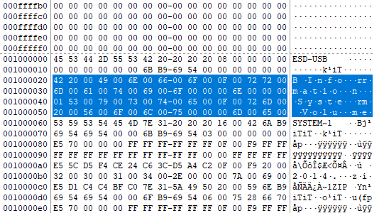
In the above image, we can see that the starting SeqNum is 42, and the 12 bytes are 0x0F. So, the two lines above are in LFN structure. The same is true for the 32 bytes below, where the SeqNum is 1. In conclusion, the LFN structure consists of two files. The way to know this is through the SeqNum, where in the case of multiple LFN structures, the last SeqNum in the 32-byte structure is 0x40 or the result of an operation. Since the SeqNums in the other LFN structures increase by 1 from 0x01, values greater than 0x40 indicate the number of LFN structures in the file through the 0x40 or operation. So, when we XOR the 0x42 again, we can see that it is 2, and the file has two LFN structures.
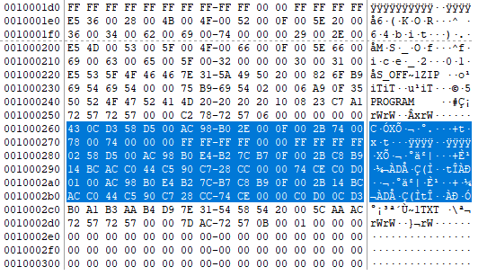
As can be seen in the example image above, it can also be calculated that the file has three LFN structures.
For NTFS, things are a little different. An NTFS partition will have a VBR, an MFT, and a Data Area. If we look a little closer, there is one VBR and one MFT, and in fact the MFT is a collection of MFT Entries. Each MFT Entry corresponds to a file or directory. The signature of an MFT Entry is FILE. If we look a little closer at the Header structure,
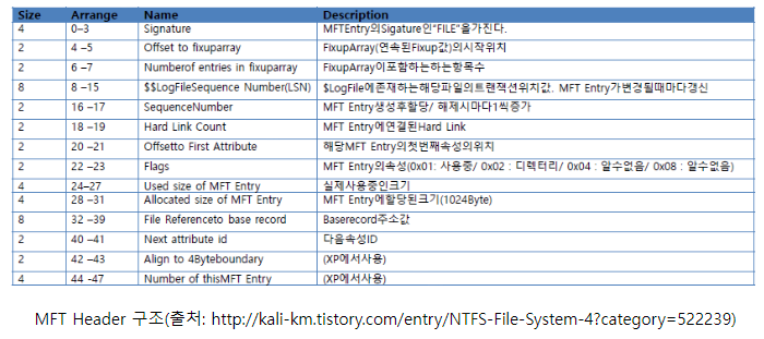
It looks like this.
In that case, I would like to introduce how to find the MFT Entry. Referring to the above NTFS VBR structure, we need to know the number of bytes per sector, the number of sectors per cluster, and the starting cluster location of the MFT Entry.
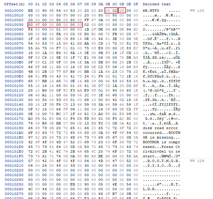
In this example, the three values required are as follows: first, 200, which means that one sector contains 512 bytes. The number of sectors per cluster is 8, which is 8. Now, the starting cluster position of the MFT entry is 6F00, which is 28,416 in integer form. So, what is the actual starting sector position of the MFT entry? Since each cluster contains 8 sectors, we need to multiply the starting cluster position by 8. That gives us 227,328. Since we are currently starting at sector 128, we add 128 to get 227,456. Now, if we move to that sector, we will see that
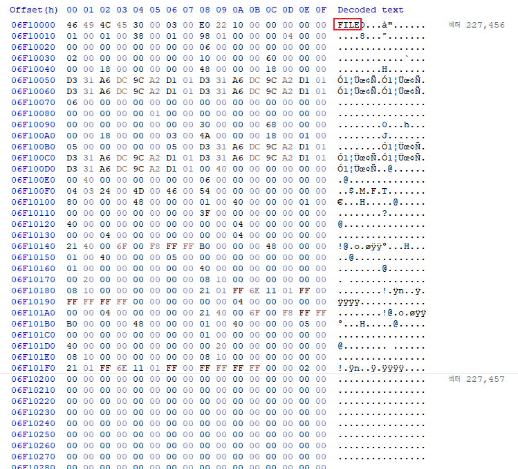
This is the signature of the MFT Entry. Now, if we look at the header of this MFT Entry, it consists of a total of 48 bytes.
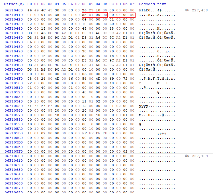
First, if we look at these two values, the first red section, which corresponds to 24 to 27 bytes, represents the actual size of the MFT Entry, and the section from 28 to 31 bytes represents the allocated size of the MFT Entry, which is 1,024 bytes (this is usually the case). The MFT Entry corresponds to a single file or directory. If we go back one sector (1,024 bytes), we see
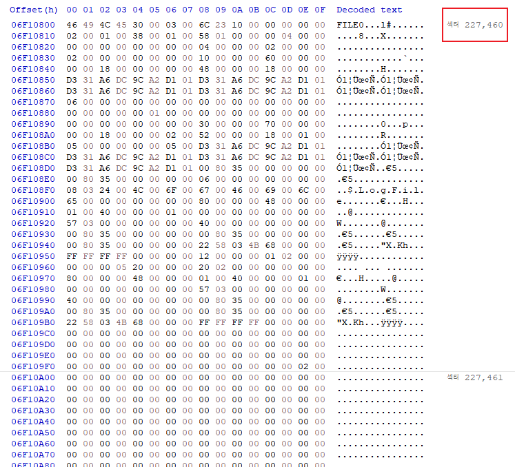
Again, we can see that the MFT Entry begins. The Fixup structure is placed after the MFT Entry Header to increase reliability. The 4th to 5th byte and 5th to 6th byte of the MFT Entry represent the value of the Fixup array and the length of the array, respectively. In hexadecimal, 30 and 3, so starting from the 48th byte, the length of 2 bytes is the Fixup value, and after that, the 3 bytes of the length calculated earlier and the Fixup value are 2 bytes each, so multiplying them gives 6 bytes as the space for storing the data replaced by the Fixup value. This Fixup value is used to find errors in advance before interpreting the data or before the contents of the sector are changed abnormally. Next, the attribute header and content are repeated, and I would like to introduce a good blog related to this.
[File System] NTFS - Part 3 (Attributes, $Properties)
Reviews
I think this will be the last post for this week. I'm still not fully understanding the structure of properties in the MFT Entry of NTFS, so I'm a bit disappointed, but I'm learning so much that I feel like I need to keep filling in the gaps.